Architectural views for software design
In this blog, I introduce the use of architectural views for software design. These are used to classify the design in different aspects of the specification.
1 INTRODUCTION
1.1 MOTIVATION
I work as an application designer in a software development team. Some time ago, I explained to the team different aspects that can be described in a system design, and their interrelationships. In this blog, I will describe a further elaboration of these aspects.
1.2 ARCHITECTURAL VIEWS
My classification is based on architectural views. What is an architectural view? What is it not? An architectural view describes a certain aspect of the design & structure of a group of organizations, an organization, a (software) system or a system component. See, for example, iotone example of architecture view.
An architectural view makes the architectural description more accessible in use: only the aspects that are important for the problem or question at hand can be studied, independently of the other aspects.
An architectural view model is not a modeling language with a meta-model. It is a categorization of a design or architecture and does not define how it can be described (e.g. with UML or archimate).
1.3 SCOPE & PURPOSE
My architectural view model is a format for the design of software systems. It can be used as a blueprint for functional and technical designs, such as use cases, use case realisations, interface specifications.
The model is not complete and I do not claim it to be complete – for example, the security aspect is not described.
2 ARCHITECTURAL VIEWS FOR SOFTWARE DESIGN
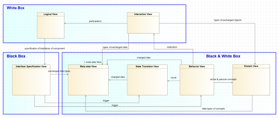
The following figure describes the architectural view model for software design
Figure 1. architectural view model for software design
This view model will be described in the following chapters.
3 EXTERNAL AND INTERNAL VIEWS
3.1 EXTERNAL / BLACK BOX VIEW
Descriptions of what is externally observable of the system, without looking at the internal workings. Examples:
-
Description of what information can be exchanged with the system
-
Description of what information can be stored in the system
-
Description of the system’s couplings to external systems
-
Description of the externally observable behavior of the system
3.2 INTERNAL / WHITE BOX VIEW
Descriptions of the internal workings of the system. Examples:
-
Description of what information is used internally, which is not perceptible from the outside.
-
Description of the internal components of the system
-
Description of the system’s internal processes and internal functions
4 DOMAIN VIEW
A domain is the defined area of knowledge and subject matter in which software plays a certain role. A domain model is an abstraction of the terms and concepts to be recognized within the domain and their mutual relationships. The purpose of this is to enable the software systems to function as well as possible within the working area of the domain. The domain model to which the system relates is described in the domain view. For example, a domain can encompass a company with all business activities, the activities of a group of companies within a sector, or a system that fulfills a certain role within a company.
It’s important to understand that a domain model is much richer than just a description of data. A concept can be pure data, for example an Assignment, with the attributes = characteristics of the Assignment, such as assignment number, start date, and so on. However, a concept can also be an active element, and be responsible for carrying out certain actions. The following is commonly described of a concept:
-
Meaning of the concept.
-
Role and responsibility of the concept.
-
Relationship of the concept with other concepts (this can be described with e.g. a UML model)
-
Rules that apply to the concept, or to the concept in relation to other concepts (business rules, rules and constraints)
-
Attributes with their meanings and types.
For the types of concepts to be identified and more information, see the book Domain-Driven Design - Tackling Complexity in the Heart of Software by Eric Evans.
4.1 RELATIONSHIPS OF DOMAIN VIEW WITH OTHER VIEWS
4.1.1 Domain view – Meta data View
The meta data view describes the data types of the concepts from the domain view, for example in the form of a model of a database.
5 BEHAVIOR VIEW
In a Behavioral View, the behavior of the system is described, in response to external triggers of actors. These actors can be other systems or users of the system with a certain role. The behavior describes what the system does, and not how it does it, usually in the form of actions that the system performs. The actions can be performed sequentially or in parallel.
The behavior can be described in different ways. Here are some examples:
-
With use cases
A use case describes the interaction between the system and actors, and the actions that the system performs. In this case, an interaction between system and actor can result in certain actions, and subsequent actions can result in a following interaction with actors.
A use case describes several scenarios. Each scenario consists of a sequence of interactions between system and actors and actions of the system. Exactly which scenario is followed depends on the states of the actors and the system and whether or not the interactions fail. The ideal scenario in which the system shows the desired behavior is called the main scenario, or 'happy flow'. In addition, various failure scenarios are usually described, in which certain errors are handled. For example, errors due to the failure of interactions with actors or the lack of certain data.
To provide an overview of the different scenarios and their interdependence, a use case usually includes a flow diagram, for example with a UML activity diagram. The actions of the system are then further explained in a separate step-by-step description.
For an example of a UML activity diagram, see star uml example of an UML activity diagram. -
Process description with archimate behavior model elements
Archimate is a modeling language for describing the architecture of companies and institutions. Broadly speaking, it describes business processes that are carried out for the provision of services to external parties. These processes are then carried out by systems and employees.
This modeling language can also be used to describe the process that a system performs for the delivery of a service. In this way, the process realizes a business function that the system offers.
For example, the process is described with 'application function' elements, as actions that the system performs, or an 'application process', as a sub-process that is executed. The service that is realized with the process is then an 'application service'. For an example of an archimate diagram, see visual paradigm example of an archimate diagram.
The behavior of the system can be both external and internal. External is the behavior that can be observed from the outside. It is the behavior that is then provided as a service to the outside world. Internal are internal actions that the system performs, and that are not observable from the outside. The external behavior (the service) can be realized by internal behavior (internal actions). With archimate, this can be modeled as an application service that is realized by a process, consisting of several functions and sub-processes.
5.1 RELATIONSHIP OF BEHAVIORAL VIEW WITH OTHER VIEWS
5.1.1 Behavior view - Domain view
A behavior view can include a description of the data mutations of concepts executed by a system, and actions performed by concepts. These are representations of concepts from the domain model in the form of data in the system or software objects from the system software. In object-oriented software, concepts from the domain model are translated 1 on 1 into classes and their mutual relationships in the business logic of the software. See the book Domain-Driven Design – Tackling Complexity in the Heart of Software by Eric Evans. From the concepts in the Behavior view, a reference is then made to the corresponding concepts in the domain model. Example:
In the Behavioral View, in a use case is described that an Assignment is created. A reference is then made to a Domain View, in which the meaning and role of an Assignment is explained. The Assignment is responsible for automatically creating a Task as part of the Assignment as soon as it is created. This is a task for a planner to schedule the assignment and create additional tasks.
5.1.2 Behavioral View – Meta Data View
A Meta Data View can describe the data types of the concepts from the Domain model. From data mutation actions in the Behavioral view, one can refer to a Meta Data View, in which the types of the mutated data are defined.
5.1.3 Behavioral View – State Transition View
If a certain action performed by the system results in a change in state of the system, the trigger that results in the change of state in a State Transition View can be referred to from the action (e.g. in a use case).
5.1.4 Behavioral View – Interaction View
In a behavioral view, in a use case, it is described what the system performs in interaction with actors (users and external systems), but not how. The system consists of various components, each of which fulfils a certain role. In response to the interactions that the system performs with actors, the components of the system start to interact with each other, with each component (according to their role) performing certain actions (defined in the use case). This is described in a Use Case Realisation. A Use Case Realisation is therefore an elaboration of a Use Case, and is part of the Interaction View (see also Interaction View). From a Use Case a reference should be made to the corresponding Use Case Realisation.
6 INTERACTION VIEW
Description of the interaction between the logical components of the system, in response to externally initiated actions that the system is required to perform. These actions are invoked via a system interface. An Interface Specification View can describe the definition of an interface.
6.1 RELATIONSHIP OF INTERACTION VIEW WITH OTHER VIEWS
6.1.1 Interaction View - Domain view
Information in the form of objects is exchanged between the components. These objects can be instances of representations of domain concepts from the Domain model.
6.1.2 Interaction View – Meta Data View
In the interaction between the components, objects are exchanged. The characterization of the data of these objects can be described separately in a Meta data View. See Meta Data View.
6.1.3 Interaction View – Logical View
From the Interaction View, one can include a reference to a Logical View with a definition of the components that interact with each other in the Interaction View.
7 LOGICAL VIEW
A logical view describes the structure of the system consisting of logical components. A logical component is a part of the system with a specific function and role. The interface couplings between the components, the couplings to the interfaces that the system provides for the outside world and to the external interfaces that the system consumes are also indicated in the view.
7.1 RELATIONSHIPS OF LOGICAL VIEW WITH OTHER VIEWS
7.1.1 Logical view – Interface Specification View
Just like the system itself, a component of the system has interfaces to communicate with other components. An interface of a system or component is described in an Interface Specification View.
8 INTERFACE SPECIFICATION VIEW
Definition of the system interfaces that allow external systems to communicate with the system. An interface specification consists of a maximum of three parts:
- Definition of the input message. This is a description of the meta-data of the message.
- Definition of the externally observable behavior of the system in response to the received message
- Definition of the output message, that the system sends in response to the received input message. The system may or may not send an output message.
8.1 RELATIONSHIP OF INTERFACE SPECIFICATION VIEW WITH OTHER VIEWS
8.1.1 Interface Specification View – Meta Data View
The meta-data of an input or output message can also be described in a separate Meta data view. This can be referred to from the Interface Specification View.
8.1.2 Interface Specification View – State Transition View & Behavior View
The description of the externally observable behavior in response to a received message or call can have a reference to a trigger in a State transition view. The interface call or the receiving of a request message is then a trigger that results in a state transition of the system. You can also refer to a Behavior view in which the behavior is described separately.
9 STATE TRANSITION VIEW
A state transition view is actually a special case of a behavioral view. It is a description of the states of the system that can be recognized, and which state transitions external triggers have as a result. It is possible that State transitions can be observed externally, but they can also remain internal.
State Transition View – Meta Data View
The states of a system are data. If the states have a certain data structure, a separate Meta data view can be referenced, which describes the data structure of the states.
10 META DATA VIEW
This is a description of meta-data of data that the system works with. This includes data that the system processes and/or manages. The meta-data description consists of:
- Description of the naming, meaning and the type of the data elements.
- Definition of the structure of the data, including interrelationships.
The data that the system works with can be:
- Data exchanged with the system (see Interface specification view)
- Data exchanged between the internal components of the system (see Interaction view).
- Data stored in the system
- Data that the system processes internally.
Examples
- An ERD (Entity Relationship Diagram) of a database of the system.
- A Unified Modelling Language (UML) class diagram, which describes data processed by the system.